Contents
Chapter 1: An Introduction to Surface Mount PCBs
Chapter 2: Advantages of using surface mount designs
- Board Space and Size
- Better Electrical Performance
- Easier Assembly
- Price Factor
- Higher Assembly Reliability
Chapter 3: Design Practices for Surface Mount PCBs
- Routing
- Component Placement
- Minimizing Loop Area and Via Stitching
- Mixed designs
Chapter 4: Common SMD Packages
- Passive Components
- Transistors and Voltage Regulators
- Complex BGA ICS
Chapter 5: How do we choose the right SMD parts?
- Passives
- High Power Components
- Connectors
Chapter 6: What OurPCB can offer
Chapter 7: Conclusion
Chapter 1 An Introduction to Surface Mount PCBs
Ever since electronics became smaller and more complex and required a larger number of components to fit on a smaller board, the industry switched from using through-hole components to surface mount parts.
Today, SMD or Surface Mount Devices have surpassed through-hole parts in terms of numbers and popularity. This article will explain in detail on how to use design boards involving surface mount parts.
Chapter 2 Advantages of using surface mount designs
2.1 Board Space and Size
Unlike through-hole components, surface-mount pads on a PCB are limited to a single layer.
What this means is, if you place a surface mount part on the top layer, then that part will have no physical presence on the bottom layer, unlike through-hole parts that have leads that go through the board and all layers.
Routing also becomes much easier as once again, the SMD component does not take up space on multiple layers. It is a huge advantage when it comes to complex multi-layer board designs.
Both these factors result in the PCB being much smaller and compact, and subsequently even cheaper to manufacture.
2.2 Better Electrical Performance
Through-hole parts often have long leads and larger pack sizes. It causes an increase in stray parameters such as the resistance, inductance, and capacitance of a component.
When it comes to high-speed designs, the parasitics of a through-hole component may cause the circuit not to function correctly.
SMD parts, on the other hand, are smaller and have much lower parasitic parameters. It makes them ideal for use in high-speed designs, and hence they offer much better electrical performance.
Components such as filter capacitors in high-speed DC-DC converters are always required to have very low stray resistance and inductance. It is where the superior SMD parts come in.
2.3 Easier Assembly
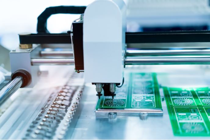
The preferred method of assembling surface mount designs has been hot air reflow soldering or sometimes even infrared heating.
In this method, a specific type of solder paste is applied on all the pads using a stencil. And then all components are placed on their pads using a pick and place machine. Finally, heat is applied, and the components get soldered into place.
The advantage with surface mount assembly is that the components are easier to place since there are no pins that need to go into holes accurately. Secondly, even if the component is slightly misaligned and not exactly placed on its pad, while reflow, the surface tension of solder paste tends to pull the component back into place.
Surface mount designs are faster to assembly.
2.4 Price Factor
One of the most expensive processes involved in PCB Assembly is drilling holes. Usually, drill bits for PCBs are quite small and need to be replaced after every few holes. In cases of through-hole designs, a lot of holes are involved, and the PCB manufacturer may charge extra for them.
However, since SMD parts do not require drilling, the resulting PCBs for them can be cheaper to produce.
2.5 Higher Assembly Reliability
There are fewer chances of assembly errors when dealing with surface mount designs. The very nature of components moving into a place with surface tension and reduced stress on the boards are due to smaller and lighter components. It means that surface mount designs end up being more reliable.
Chapter 3 Design Practices for Surface Mount PCBs
3.1 Routing
Traces for surface mount designs can be much thinner than through-hole parts as they don’t terminate onto a drilled hole and hence experience less stress.
Additionally, traces should route in a way such that they stay on the same layer as the component and change layers only unless it is required.
3.2 Component Placement
There are two main approaches to placing surface mount components:
- Placing all components on one side for easier assembly. In this approach, most if not all components will be placed on either the top or bottom side so that assembly and soldering have to do on one side of the board. It can reduce assembly costs to some extent.
- Two-sided board, here the components are placed on both sides of the board. It results in smaller board size and so reduced PCB fabrication costs. It can also be useful for high-speed designs that need to be compact to minimize inductance and resistance.
3.3 Minimizing Loop Area and Via Stitching
The following two ways can complete it.
- You are having continuous ground planes wherever possible, along with internal power and ground planes.
- It is extensive via stitching between the top and bottom layers which would interconnect all the ground points.
Both of these methods reduce the path that the return current must take, reducing the noise emitted by the board.
3.4 Mixed Designs
Sometimes, through-hole parts are required to be used in a surface mount design as well. It can be either for certain connectors or headers that are only available in through-hole configurations. As well as for some high current semiconductor devices that benefit from through-hole packages. It allows them a higher current carrying and heat sinking capability.
These called mixed designs. Common products that use these are high-power devices such as inverters and motor controllers; as well as products that require through-hole connectors such as Arduino and Raspberry Pi shields.
Chapter 4 Common SMD Packages
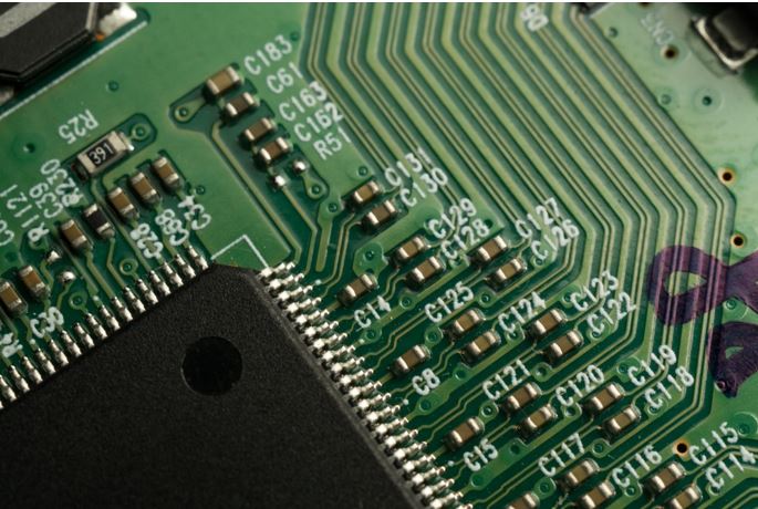
4.1 Passive Components
The common passives like capacitors and resistors come in standard packages. Some of the popular ones are 2512,1206,0805,0603,0402 etc. These numbers represent the length and width in inches.
So a 1206 package is 0.12inches long by 0.06 inches wide.
There is even a smaller presence, and it used in mobile phones and tablets. These are 0201, 01005, and finally, 008004 being the smallest currently available.
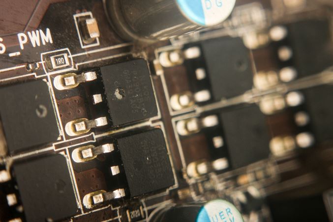
4.2 Transistors and Voltage Regulators
Transistors and voltage regulators come in a wide variety of packages.
The common ones are usually,
SOT23, DPAK, D2PAK, SOT223, and SOIC.
These features are chosen based on size and power handling capabilities.
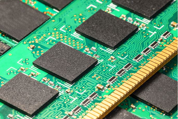
4.3 Complex BGA ICS
Finally, complex ICs and processor chips come in a high-density ball grid array or BGA package. These packages expose connections at the bottom of the chip, so the only way to solder them to the board is to use a heat gun. A soldering iron cannot handle them. These packages also require a good routing strategy and often, multi-layer board stack up to route all pins.
Chapter 5 How do we choose the right SMD parts?
5.1 Passives
Choosing SMD passives depend on the type of board you are designing,
For producing only a small amount of amateur boards, sizes like 1206 are convenient as they are large enough to solder and handle by hand.
For high speeds designs and dense boards, where a lot of components are needed, smaller parts such as 0603 and below may need to use. These boards are often made in larger numbers and assembled at factories.
5.2 High Power Components
High power components in SMD packages usually come with an exposed pad for thermal conduction and enhanced heat sinking capabilities.
Discrete Mosfets that need to handle tens of amps (as in BMS applications) typically selected in DPAK and D2PAK style packages. These are also suitable for voltage regulators.
More complex ICs preferred in a SOIC package with an exposed pad for heat dissipation.
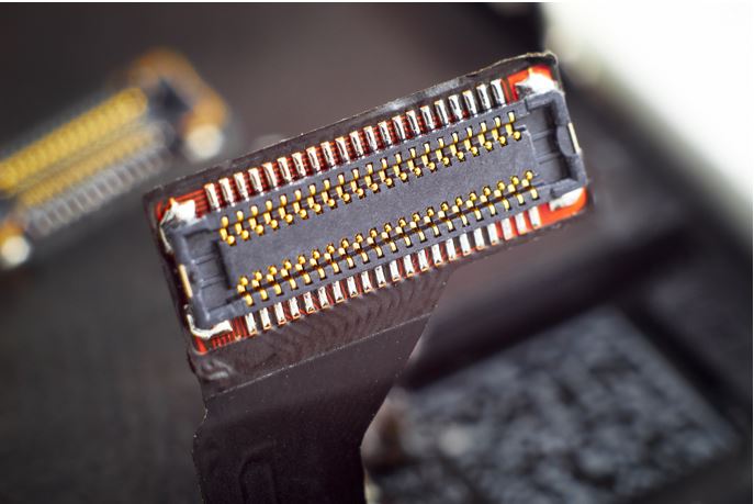
5.3 Connectors
Choosing connectors is mainly dependant on the amount of stress they need to handle and their current ratings.
Board to board connectors can often be surface mount like SMD type JST connectors. The connectors exposed in the product are usually a mixture of through holes and SMDs, such as USB connectors on most mobile phones.
Below is a link to video demonstration of soldering an SMD connector
https://www.youtube.com/watch?v=CVPEHgfeoGE
Chapter 6 What OUR PCB offers
SMD Component Assembly
OurPCB has a very capable assembly setup which can handle even smaller components that are popular today. The smallest component we can accurately mount is 0201. Our Assembly service saves time and money for both hobbyists as well as large companies.
Online Quotation System
Finally, OurPCB also has an online quotation system that automatically calculates the price of your PCB after you upload your Gerber files and input the required data.
It can achieve very fast order generation time, and your board to complete the manufacture in the shortest possible time.
Chapter 7 Conclusion
Surface mount PCBs is the current best choice for all designs as they result in a smaller, more reliable, and better functioning product along with cheaper costs of manufacturing.
OurPCB offers the perfect balance between price and quality, along with multiple manufacturing options.
For more information, please contact us immediately.